
 CN
CN

+86 13963667529
+86 13963667529

 +86 13963667529
Product Introduction
★ High vacuum degree (vacuum degree of 0.09~0.098MPa), resulting in low filter cake moisture content.
★ Filtrate solids content <50ppm, reusable and reducing emissions.
★ Energy savings of over 90% compared to traditional filtration equipment, with low energy consumption and operating costs.
★ Additional filter cake washing compared to traditional ceramic filters, suitable for materials requiring washing.
★ High automation level using PLC and microcomputer combined with automatic valve control, reducing labor intensity.
★ Compact structure, small footprint, and easy installation and maintenance.
★ Drainage system suitable for use under any working conditions.
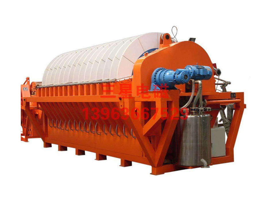
The structure of a ceramic filter mainly includes: The ceramic filter mainly consists of a rotor formed by several groups of ceramic filter plates, a distribution head that generates suction and washing effects through self-coupling switching, a stirrer to prevent solid sedimentation, a scraper to remove solids adsorbed on the filter plates, a tank to maintain a certain slurry level, and an operating program control system.
During operation, due to the vacuum effect, the filter plates form a layer of solid particle accumulation on their surfaces when rotated and submerged in the slurry level within the tank. The liquid passes through the filter plates and is switched by the distribution head into the vacuum bucket. When the filter plates with the accumulated layer leave the slurry level, a filter cake is formed, which continues to dehydrate due to the vacuum effect, further drying the filter cake. The rotor continues to rotate to the position equipped with the scraper, where the filter cake is unloaded and sent to the required location by a belt conveyor.
After unloading the filter cake, the filter plates rotate to the washing position where the self-coupling switches to a flow opposite to the vacuum direction, forming a washing effect from the inside of the filter plates outward to remove particles blocked in the ceramic micropores. They are then re-immersed in the slurry.
After prolonged operation, the filter plates can be washed using a reverse washing liquid to which chemicals can be added to maintain the filter's operation.
Technical parameters
| Model Area | Filter Discs (Rings) | Number of Filter Plates (Pieces) | Tank Volume (m³) | Installed Power (KW) | Operating Power (KW) | Host Machine (L*W*H)m |
| TH-1 | 1 | 12 | 0.21 | 3.5 | 2 | 1.6*1.4*1.5 |
| TH-4 | 2 | 24 | 1 | 7 | 3 | 2.4*2.5*2.1 |
| TH-6 | 2 | 24 | 1.2 | 7 | 6 | 2.4*2.9*2.5 |
| TH-9 | 3 | 36 | 1.7 | 9 | 7 | 2.7*2.9*2.5 |
| TH-12 | 4 | 48 | 2.2 | 11 | 7.5 | 3.0*2.9*2.5 |
| TH-15 | 5 | 60 | 2.7 | 11.5 | 8 | 3.3*3.0*2.5 |
| TH-21 | 7 | 84 | 4 | 13.5 | 9 | 4.6*3.0*2.6 |
| TH-24 | 8 | 96 | 4.5 | 16.5 | 10.5 | 4.9*3.0*2.6 |
| TH-27 | 9 | 108 | 5 | 17 | 11 | 5.2*3.0*2.6 |
| TH-30 | 10 | 120 | 5.5 | 17.5 | 11.5 | 5.5*3.0*2.6 |
| TH-36 | 12 | 144 | 7 | 23 | 16 | 6.6*3.0*2.6 |
| TH-45 | 15 | 180 | 8.5 | 15 | 19 | 7.5*3.0*2.6 |
| TH-60 | 15 | 180 | 12.5 | 33 | 22 | 7.5*3.3*3.0 |
| TH-80 | 20 | 240 | 16.5 | 40 | 24 | 9.0*3.3*3.0 |
| TH-102 | 17 | 204 | 18.5 | 53 | 35 | 8.8*3.6*3.3 |
| TH-120 | 20 | 240 | 20 | 60 | 40 | 9.7*3.6*3.6 |
| TH-150 | 25 | 300 | 24 | 75 | 47 | 11.2*3.6*3.3 |
Phone: +86 13963667529
E-mail:13963667529@139.com
Web:www.wfsanxing.com